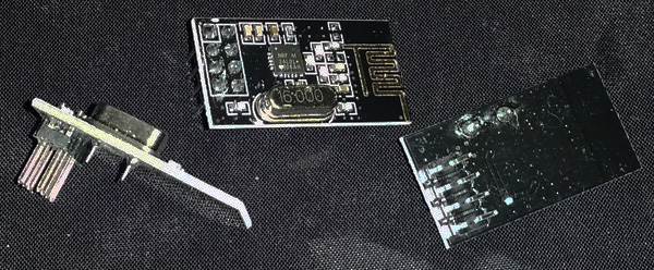

Below should be everything you need to know in order to assemble a KTRL Wireless CD32 Receiver. It all comes down to these steps: Get the needed parts, solder the components, program the microprocessor* and finally, put it all together.
*) or get the microprosessor preprogrammed from me.
I will be able to supply a limited amount of these modules. You can also find them on itead.cc, eBay, Aliexpress etc. There exist counterfeit versions of the chip used on this module that are not as good as the original, ITEAD are selling modules with original chips, I buy them from there. These go for around 2 to 3€ a piece.

You can order the PCB from me on Amibay.com.
The microprocessor used by the KTRL CD32 is the Atmega328P-AU (TQFP-32 package). You can buy this from eBay, electronic component retailers or buy them preprogrammed from me on Amibay.com.

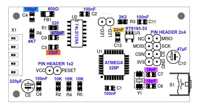
I also sell the other electronic components needed in the same Amibay.com thread as a set. The layout image below shows the needed parts if you want to buy them from somewhere else.
The "KTRL CD32" logo sticker is included when you buy the PCB in the Amibay.com thread.
To program the Atmega you will a USBAsp programmer. These are very cheap and available readily on eBay. Search for "usbasp" and you should find them for less than 2€. For this you also need Dupont jumper wires (Female-Female) or you can use the cable supplied with the USBAsp with a 10pin to 6pin adapter (used for Arduino). Search on eBay for "dupont male female". Note that if you buy the Atmega preprogrammed from me you don't necessarily need this but I might release updates to the firmware later.

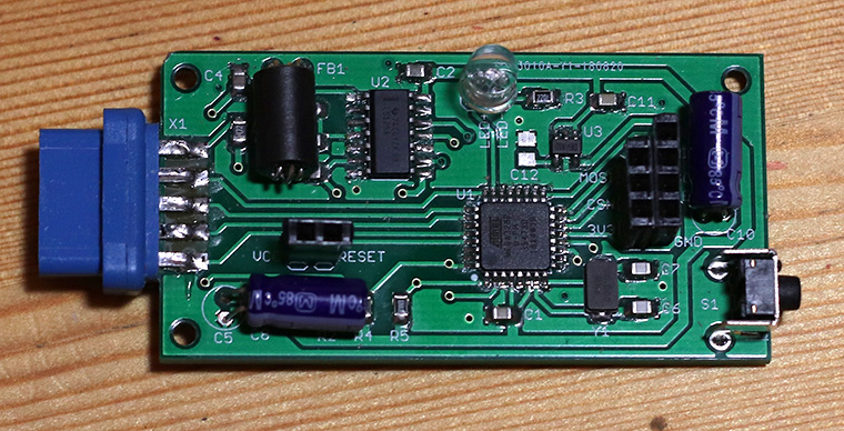
If you want, you can remove the metal surrounding the connector (see picture of assembled PCB below). You can do it by bending the metal around the holes back and forth, it should break after a few bends.
Solder the the PCB components according to the following layout. SMD capacitors (if you bought a kit from me) are either marked with codes or colours as in the layout image. If you are going to 3D print a case for the receiver, then solder the LED so the top of the LED is about 1mm higher than the top of the pin headers.

Soldered PCB, note that some components might differ from the ones you have received.

When all components etc. are soldered, give the PCB a proper clean with rubbing alcohol, the flux residue can cause noise in the circuit. Check for any shorts between the legs of the Atmega. Verify the polarization of the electrolytic capacitor a final time.
Connect the USBAsp to USB port. Don't try to find a driver, cancel the automatic driver install if possible.
Download and run Zadig for easier driver installation: http://zadig.akeo.ie/
In Zadig, choose USBAsp in the drop-down list. If you can't see the device in the list, go to the Options menu and select List All Devices, be sure to select the correct device.
Select driver "libusbK (v3.0.7.0)" and click Install Driver (or Replace Driver). If you get a security alert, choose to install the driver anyway.
Download the latest firmware here and AVRDude (for Windows) here. If you use Mac OS or Linux you need to install AVRDude, there should be tutorials how to do this.
Connect the USBAsp to the pin headers with the dupont wires according to to the picture below, then connect the USBAsp to a USB port of your computer.

You then need to run these commands in a command prompt / shell (from the folder where you extracted the firmware):
// Erase the chip (only needed if chip is not empty). This is done at a slower speed (-B 3)
avrdude.exe -p m328p -c usbasp -P usb -B 3 -e
// Set the fuses to enable external crystal etc. This is done at a slower speed (-B 3)
avrdude.exe -p m328p -c usbasp -P usb -B 3 -U lfuse:w:255:m -U hfuse:w:223:m -U efuse:w:5:m -U lock:w:63:m
// Write the firmware
avrdude.exe -p m328p -c usbasp -P usb -U flash:w:"KTRL_Wireless_Receiver_CD32_v100.hex":a
(The LED on the KTRL should blink twice when programming is finished)
Cover the PCB and the radio module with heat shrink tubes and cut out holes for the LED and pin headers after shrinking the tubes using heat (the receiver in the photo might differ a little from your receiver). The sticker can either be installed on your gamepad or the bottom side of the receiver.

Alternatively. you can print a case for the receiver if you have a 3D printer. The model can soon be downloaded from Thingiverse.